THE ILLUSION AT A GLANCE
The Metamorphosis Cabinet uses a vertically mounted clear acrylic reflector, two aligned subjects, independent lighting, and controlled sightlines to make one figure appear to transform into another in the same apparent position.

STEP 1 — BUILD THE CABINET SHELL
Build the six-panel plywood cabinet shell to the locked dimensions, measure actual plywood thickness before final cutting, and square the shell by checking both diagonals.

STEP 2 — CUT AND FRAME THE VIEWING APERTURE
Cut the centered 14 × 26 inch viewing aperture in the front panel, positioned 5 inches above the interior floor reference.

STEP 3 — INSTALL THE ADJUSTABLE REFLECTOR MOUNT AND HIDDEN-CHAMBER PARTITION
Install the adjustable reflector mount at the nominal 45-degree plan-view position and add the mandatory floor-to-ceiling hidden-chamber partition.

STEP 4 — DRY-FIT THE 24 × 36 CLEAR ACRYLIC AND ESTABLISH VIEWING POSITION
Dry-fit the 24 × 36 × 1/8 inch clear acrylic vertically on the diagonal reflector mount and establish the intended 24–36 inch viewing position.

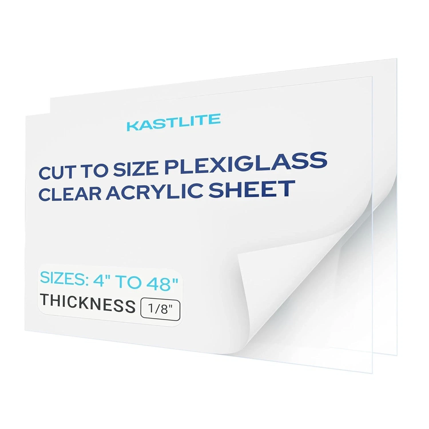
KASTLITE clear acrylic — clear 1/8 inch × 24 × 36 inch, one pack
This is the clear vertical reflector panel.
STEP 5 — INSTALL AND ALIGN FIGURE A AND FIGURE B
Position Figure A and Figure B at matching base elevation and compatible scale, then align Figure B’s reflection over Figure A from the actual viewing position.

STEP 6 — BLACK OUT THE CHAMBERS
Black out the chambers with plush velvet and matte-black surfaces, seal gaps and bright hardware, and control stray light with baffling.
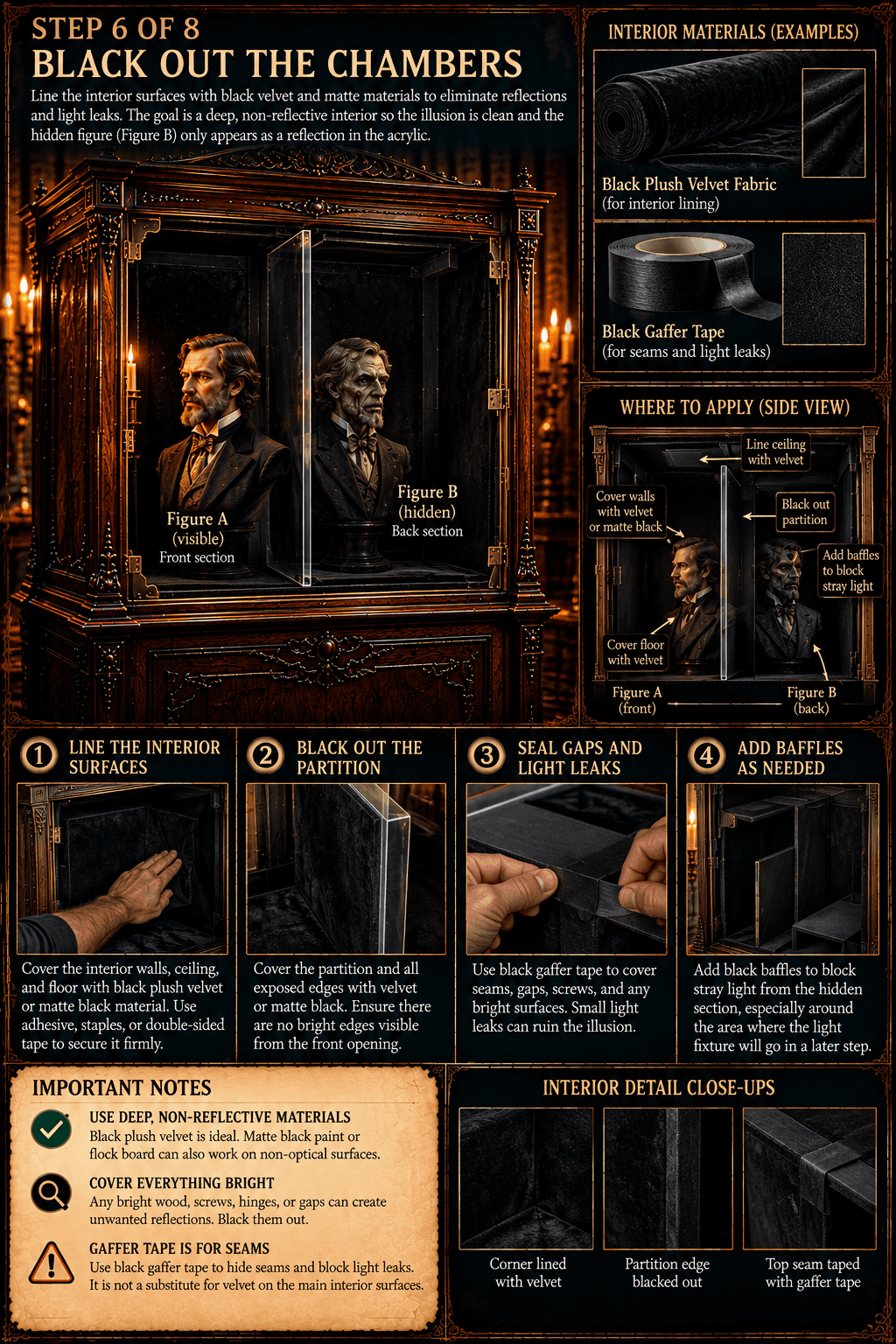
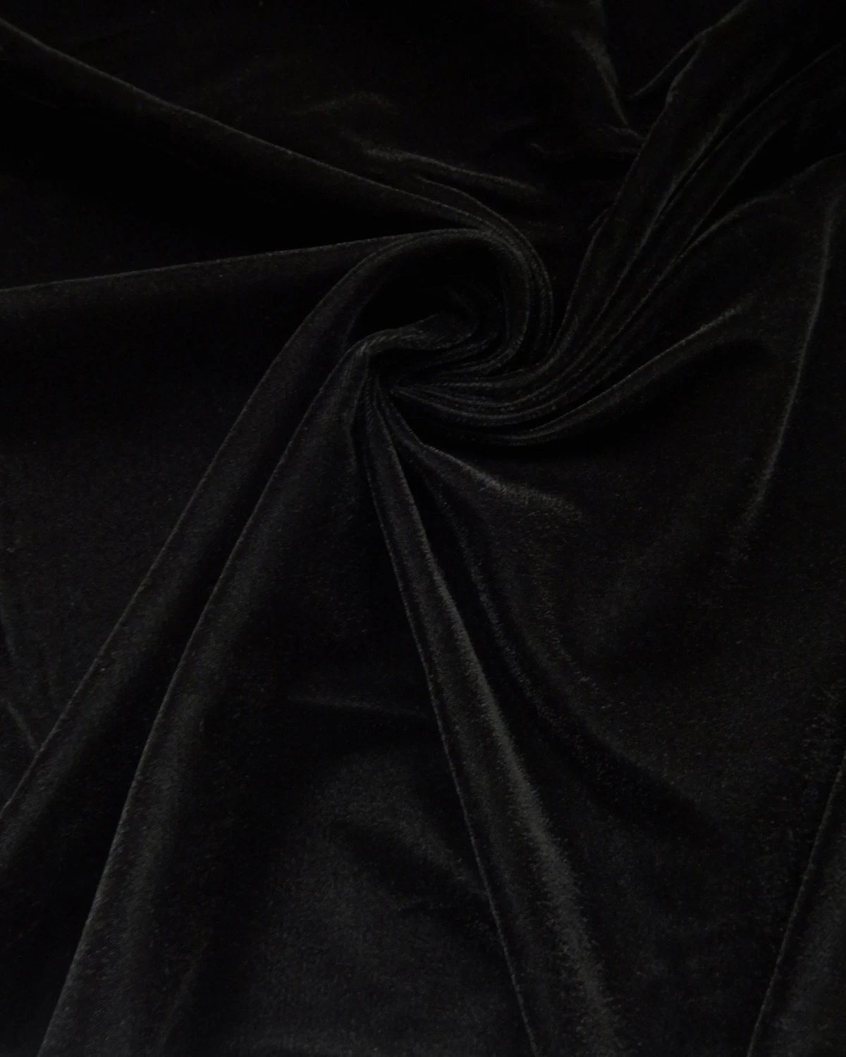
Black plush velvet — 45 inches wide, sold by the yard
This is the primary light-absorbing lining.
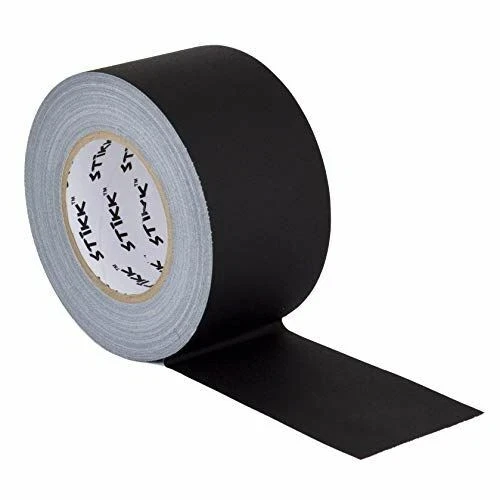
STIKK black gaffer tape — 3 inches × 60 yards, 11 mil matte no-residue cloth tape
Use it for seams, gaps, bright fasteners, edge treatment, and small light leaks; it is not primary blackout material.
STEP 7 — INSTALL INDEPENDENT LIGHTING AND CONTROL
Install two independently controlled RGBW PAR lights, fully shroud the hidden fixture, and balance the two subjects by apparent brightness from the viewing position.

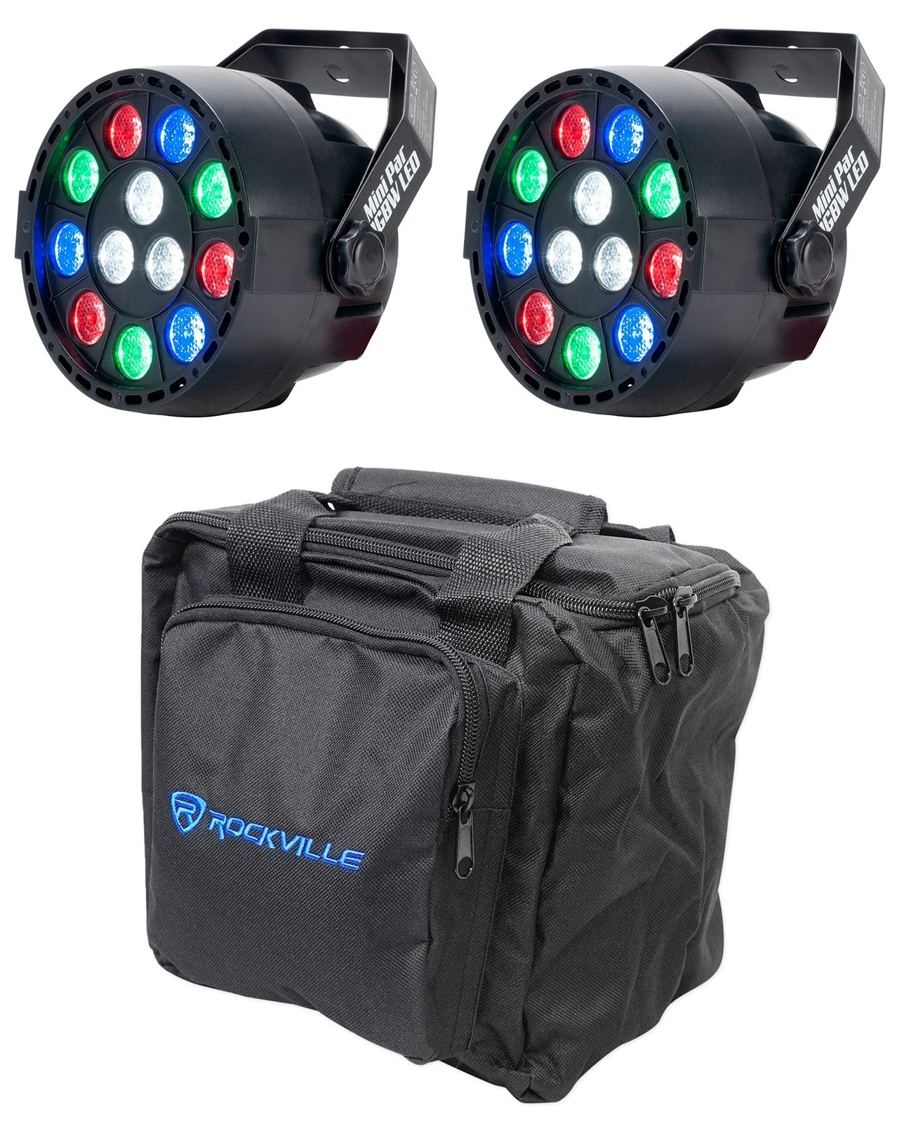
Eliminator Mini Par RGBW LED pair
This is the two-fixture independent RGBW lighting pair.
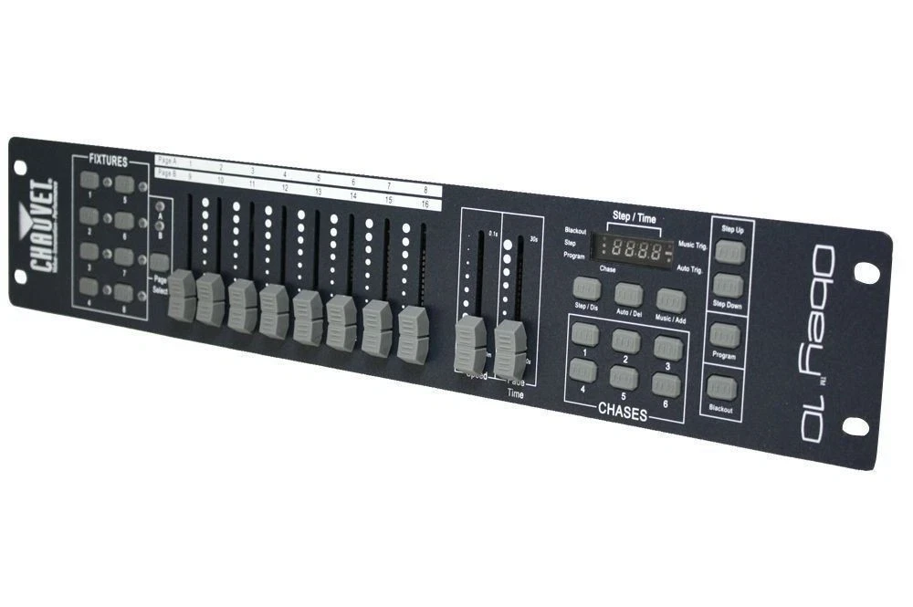
Chauvet Obey 10 controller
It controls the two lighting channels for the crossfade.
STEP 8 — CALIBRATE, TEST, TROUBLESHOOT, AND LOCK
Run the full transformation, correct alignment and light leaks, verify the viewing position, then secure the reflector, fixtures, cables, subjects, and baffling.
